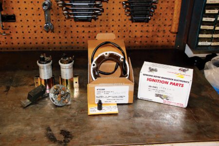
There comes a time when practicality overcomes originality, and a good example of that is our project for this issue, converting a 6v Energy Transfer (ET) ignition Triumph over to 12v while retaining the original no-battery look of the ET system. For that we used a 12v Lucas alternator and a Boyer Power Box, both sourced from Klempf’s British Parts in Dodge Center, Minnesota. I explained to Mitch Klempf that I wanted better lighting, but didn’t want to alter the look and he agreed that changing the alternator and putting a Power Box up under the seat would keep the look while allowing me to see the road ahead at night. This How To will show you how you can do this too if needed or wanted.
— Keith Fellenstein
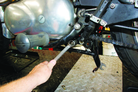
1. We’ll begin by removing the left footpeg and lowering the brake lever for access to the primary drive and alternator.
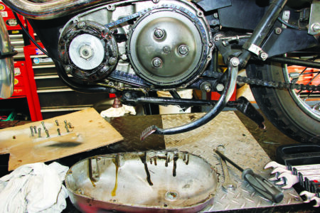
2. You’ll also need to slacken off the primary chain tensioner and drain the oil from the primary. As the primary screws are of various lengths, it helps to draw a schematic on a piece of corrugate and punch the screws through in their proper places.
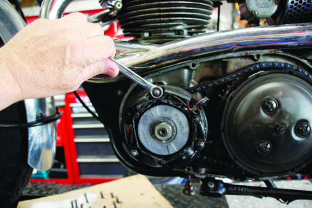
3. Remove the nuts holding the alternator in place. Disconnect the five leads from the wiring harness and remove the alternator. Due to age and heat, the wires and sealing thimble may be stiff. Gentle heat from a heat gun can soften things up for easy extraction.
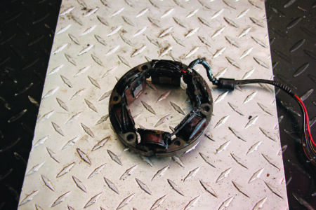
4. The original ET alternator was unencapsulated open wiring and most have failed by now. The original ET coils likewise had perished and had been replaced with EMGO coils that worked in the same way as the originals. This alternator appears to have had some epoxy applied to it in the past.
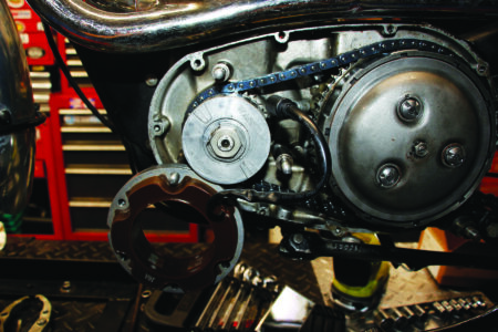
5. Hang the new alternator temporarily from one of the studs and feed the wires first through the new sealing thimble and then the inner primary case. It can be hard to feed the wires through, you may have to strip away some of the PVC jacketing to allow you to pass them through one at a time.
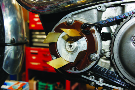
6. Clearance between the rotor and the alternator is vitally important. You must have .008-inch clearance around the gap between the two. Using a single feeler gauge is not enough. A better method is using a piece of shim stock .008 inch thick and getting enough for 4 strips. I couldn’t find plastic of the correct thickness, so I bought brass shim stock and added adhesive tape to reach .008. When you have the correct clearance, tighten the alternator bolts to 20lb/ft.
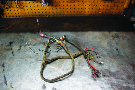
7. After some disassembly it was apparent the original wiring harness was butchered beyond use, so we are moving forward with a new one.
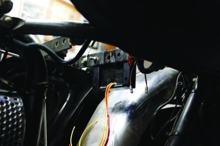
8. Find a place to mount the Power Box. We put it here, where the battery would be if we had one. Attach the two leads from the new alternator to the yellow leads into the Power Box. This is AC so it doesn’t matter which lead from the alternator goes to which yellow lead.
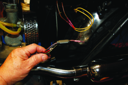
9. Now comes the tricky part, wiring. We’re turning an unregulated low output AC system into a fully regulated high output DC system. We begin with the alternator, the old system had five wires from the alternator. Four of these wires carried AC current and the red one was the ground. The easiest way to use the old harness (or a new one) is to connect all four of those wires to the black lead from the Power Box. That powers up all the wires with -12v. We’re keeping it positive ground for simplicity’s sake. Connect the red lead to the red lead from the Power Box.
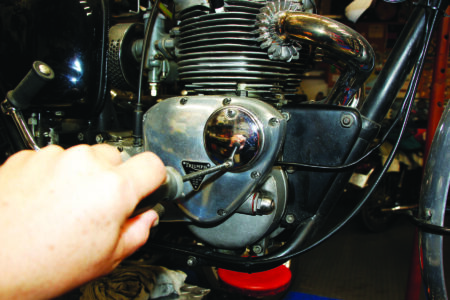
10. Remove the points cover for access to the points plate, auto advance unit and points wiring. Remove the pillar bolts and pull the points plate out of the cavity. Disconnect the points wires.
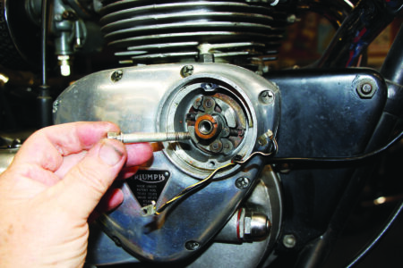
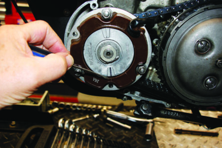
11. Remove the bolt holding the auto advance unit to the cam. Ideally you will use the auto advance extraction tool shown in the next step to pull the advance unit out.
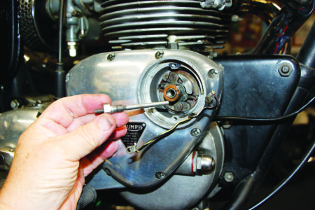
12. Start by loosely threading the tool into the threaded portion of the advance unit. Then screw the inner pin in until it touches the end of the cam inside the timing cover. Tightening the bolt then will break the taper connection holding the advance to the cam. If you don’t have the tool, you can thread a 5/16-inch x 24 bolt into the end of the advance unit and gently tap it from the side to break the taper connection.
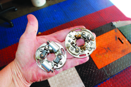
13. Due to the odd nature of the ET system, we will have to make some changes to the points wiring. We’re also taking this opportunity to change from the old 4CA points plate to the newer 6CA points plate with individually adjustable points timing.
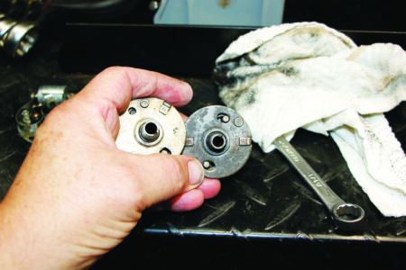
14. We’re changing the old 5 degree advance to a 12 degree advance, taking advantage of the steady 12v from the Power Box. The advance is limited with the ET ignition due to the need to fire the coils at the peak of the AC waveform from the alternator.
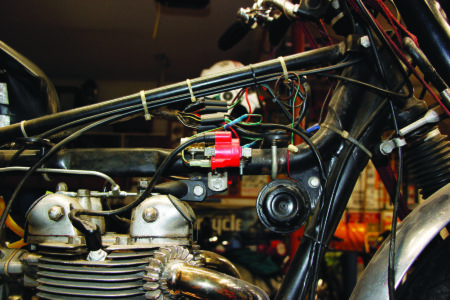
15. The ET coils (modern version by EMGO) will be replaced by a pair of 12v Lucas coils I had in my junk box. Both bench tested ok.
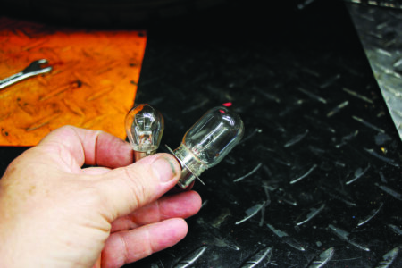
16. New 12v prefocus headlight bulb and standard 12v tail/brake light bulb. Also, a 12v instrument bulb (not shown). The old 6v horn will work ok on 12v for the intermittent use it gets.
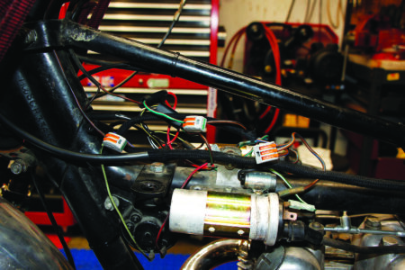
17. Mount the coils. I had modified extra condensers for the ET system, they can be repurposed for the new system. Alternatively you could use a Lucas 2 condenser pack. The wire fasteners are a more modern version of wire nuts, and work very well to connect where you don’t have Lucas bullet connectors to use.
18. With the alternator bolted up, find TDC on the piston closest to you. You can use a TDC tool as we did, or a soft piece of wire. When you have found TDC, mark a point on the alternator opposite the lower rotor mark. Also mark the wire or screwdriver. Measure up on the tool 8.4mm or .330 inches, this will be full advance. Rotate the engine backwards until the top mark is aligned with the spark plug hole. Make another mark on the alternator opposite the lower rotor mark. This is full ignition advance.
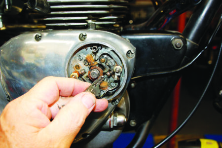
19. On the timing side of the bike, look at the points in the points cover. One set should be open and the other closed. Using a feeler gauge, set the fully opened points to .014 inches. Rotate the engine one revolution and repeat for the other set of points. You now have the points gap set correctly.
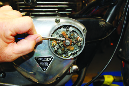
20. Use a small screwdriver to push the advance to fully advanced on the set of points not yet opened. They should just open as you reach the end of the travel. If they don’t, or if they open sooner, move that set of points until they are just opening. Lock them down.
21. Rotate the engine one revolution and repeat the last step for the other set of points. Now you have set the static ignition timing. This bike has no easy way of doing dynamic timing, no indicators other than the ones we just put on the alternator. Later machines have a window and pointer you can use with a timing light to double check your work. The original alternator has separate ignition and lighting circuits. The new one doesn’t, so starting is easier if you remember to turn off the headlight at the bucket switch. That’s it. All done!

