As we get older, it’s a fact that our desire to ride our classic bikes can be in conflict with our ability to kickstart them. For some of our classic bikes, there are aftermarket electric start options. Some of the very last Triumphs, twins and triples, had electric starters. Until now though, there’s never been an aftermarket kit to retrofit earlier Triumph twins with an assisted kickstart. Those of us with artificial joints (hips, knees, etc.) who still want to ride but don’t want to risk physical injury due to kickbacks can finally find some relief. The Classic Bike Experience in Essex, Vermont, American importers of the Alton starter for Norton motorcycles, have developed an air-powered kickstart assist. Once installed, you will still be using the kickstarter, but the effort will be greatly reduced. We’ll show you how to install it on a 1968 Triumph Bonneville.
The installation of the electronic controls is fairly easy. Slightly more time consuming is the careful placing of the actuator itself. Keep in mind that though these machines left the factory fairly standard, years of modifications and restorations may have changed them. Be prepared to do some fitting. The instructions supplied with the kit are detailed and well illustrated.
It’s also helpful to have a compressed air supply available for testing this system during assembly. If you have a shop compressor, or even a small pancake compressor, that will do. Plan on a full day’s work, and as always, the relevant shop manual and parts diagrams are very helpful for parts identification and proper torque specs. The air bottle can be filled at your local scuba shop with high-pressure air. We had our bottle filled to 4,500psi before starting the installation.
For more information on the inspiration, design and prototyping of the KickMagic system, read an online exclusive story.
Watch this short video to see how easy our Bonneville started after installation.

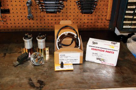
1. Here are the contents of the kit laid out before we get started. The leather satchel holds the air bottle. There are also several bags of nuts and bolts not shown.

2. Start as always by disconnecting the battery. For this installation, it’s necessary to remove the battery tray so that the solenoid can be installed in the space below the tray. Continue and remove the side cover, gas tank and kickstart lever too.

3. Remove the bolts holding the handlebar P-clamps in place and raise the bars far enough to be able to pass the control cable socket under one side.

4. Install the control panel using the two socket head bolts from Bag D. Run the wiring harness forward under the bars and then left along the frame tube toward the side cover where they will connect to the control box. Use the supplied zip ties to tidy up the wiring.

5. Test fit the solenoid bracket to the solenoid. Assemble the solenoid clamp and bracket to the frame down tube, leaving at least 1 inch of clearance under the battery box.

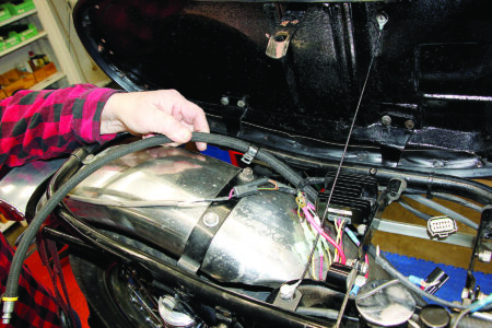
6. Route the 32-inch inlet hose up and back along the rear fender, clamping it to the rear fender brace with the supplied clamp. Thread the 20-inch outlet hose in front of the oil lines from the bottom of the oil tank and clamp it to the top engine mounting bolt using the supplied clamp.

7. Connect the main harness to the solenoid assembly and proximity sensor assembly. Route the proximity sensor and cable to the right side of the bike following the outlet hose but leave it hanging for now. Run the power leads forward along the top frame tube.

8. Our test bike has been converted to 12v negative ground, so our fuse lead is on the positive side of the battery. Regardless of how it’s grounded, red goes to positive, black to negative. In our bike, we connected the red lead to the white switched power lead on the ignition coil. The KickMagic is designed to work with both positive and negative ground electrical systems, just follow the instructions appropriate for your machine.

9. The black lead was connected directly to a good frame ground, which we made from a ring connector and a female spade connector joined by a piece of copper wire.

10. Fit the supplied rubber strip to the lip of the tool compartment. Carefully press the electronics module into the space formerly occupied by the tool roll. It’s a snug fit, so take your time and work it in place.

11. Connect the wiring harness to the two terminals of the control module. The harness is keyed so you can’t make a wrong connection.

12. The actuator mechanism mounts to the kickstart shaft and extends it so you can refit the kickstarter. It’s important to make sure the mechanism is a good sliding fit on the starter shaft. Due to years of use it may be necessary to use emery cloth, a file or a Dremel tool on the starter shaft to remove and smooth any burrs. Take your time and get it right without going too far. We were lucky; ours was in good shape.

13. Now that the controls are in place it’s time to test the electronics. Turn on the key and you should see the LEDs on the control panel sequence three times red, amber, green. Press the left button and the red LED should light. Hold the proximity sensor near a piece of steel and the amber LED should light. Press the right button and the green LED should light and you should hear the solenoid engage for five seconds.

14. The boost cylinder mounts over the engine plate, using the supplied spacers, and replaces the muffler plate. We found that the longest engine mounting bolt supplied was not long enough to reach through the proximity sensor mounting plate, through the rest of the kit and allow for a washer and the nylock nut on the inside so we used a longer bolt not shown here.

15. After placing the booster assembly on the frame, snug down the bolts and carefully check the alignment between the boost cylinder and the chain. This is where the fitting we mentioned earlier will come into play.

16. Attach the air hose to the boost cylinder using the supplied teflon tape and a 3/4-inch wrench.

17. Install the proximity sensor and align it with the inner rim of the chainwheel. Pull the kickstart lever back slightly and arrange for a .040-inch gap between the sensor and the rim of the chainwheel.

18. Install the satchel and air bottle and connect the air bottle to the air line. Turn the low pressure regulator knob until the pressure gauge reads about 50psi. Test the system again as in Step 13. This time you should see the air cylinder pulling the kickstart lever back.

19. Final calibration of the air pressure is trial and error. With too much pressure the air cylinder will try to initiate the kick without you. With too little you expend more effort than needed. After testing at 50psi (shown), set it to 85psi. That’s a good place to start and you can adjust up or down from there as needed.

20. Turn on the ignition, wait for the system to reset, then press the left button to arm the system. Slightly depress the kickstart to the point of compression, look for the amber light to be lit, then press the right button to charge the cylinder. With just an easy press on the kickstarter, the cylinder takes over most of the effort.

21. Here is the finished installation. At first glance you hardly notice the add-on, and it doesn’t look out of place when you do. If you need help getting your 650 or 750 Triumph twin started, this could be the answer.


